
Deburring & Edge Finishing
Every cutting operation leaves a burr, and deburring is what removes it — by hand, in a vibratory tumbler, or with a machine that follows the cut path. It matters for three separate reasons: handling safety, assembly fit, and corrosion, because a burr traps moisture and a coating hangs thin on a sharp edge. On parts that will be coated, deburring is a prerequisite rather than a finishing touch.
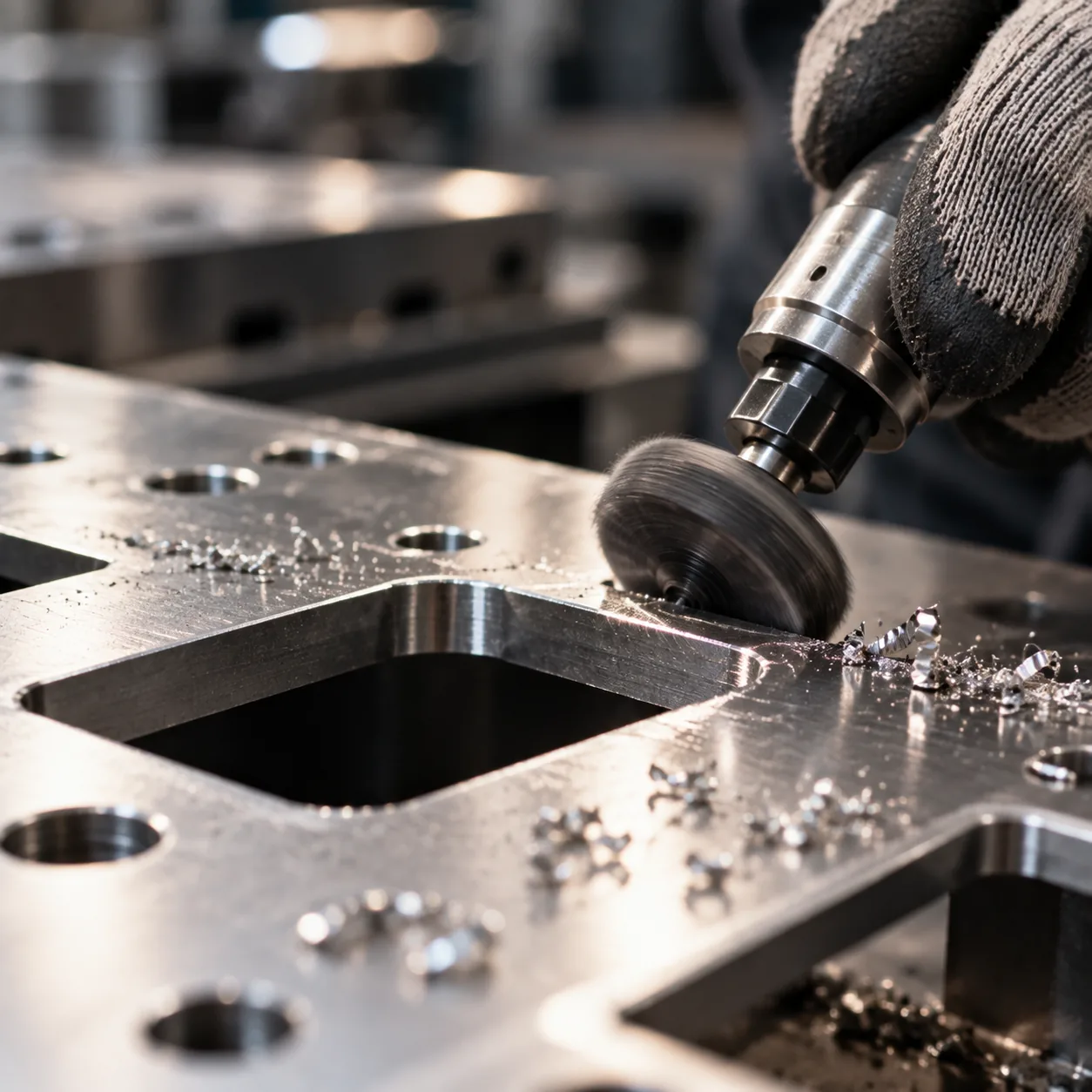
Deburring removes the sharp raised edge that every cutting operation leaves behind. It is done by hand where the edge is complex or the quantity is small, in a vibratory tumbler for batches of parts that can be tumbled, or with an abrasive brush that follows the cut path on larger sheets. It is not cosmetic: a burr injures the people handling the part, stops faces from seating properly, and gives a coating nothing to hold on a sharp edge.
Why does every cut leave a burr?
Laser cutting leaves a dross edge and a heat-affected zone, punching tears the material as the punch breaks through, and shearing leaves a roll-over on one side and a fracture on the other. Each of those mechanisms pushes metal rather than removing it cleanly, and the displaced metal stays attached to the part. The size of the burr depends on the process, the material and, above all, on how sharp the tooling is.
Which deburring method suits which part?
Hand deburring with a rotary tool or a file reaches edges a machine cannot, and suits one-off parts and complex profiles. Vibratory tumbling puts a consistent radius on every edge of a batch of smaller parts at once, and is the most repeatable method at production quantities. Abrasive brushing is used where the edge has to follow a specific cut path on a large sheet, and edge milling produces a controlled, machined edge where the drawing specifies one.
What should the drawing specify?
If the drawing is silent, the part is deburred to remove sharp edges, which is the safe default. Where function depends on it, specify the edge: a maximum burr height, a required edge radius, or a note that edges must be broken by a defined amount. Being precise matters most on mating faces, on parts handled during assembly, and on anything that will subsequently be coated.
Why deburr before coating?
A sharp, burred edge is the hardest place for a coating to cover, and it is the first place a coating fails in salt spray. Deburring puts a radius on the edge, which lets powder or paint wrap around it and hold at full thickness instead of thinning to nothing at the tip. On coated parts, deburring is therefore a prerequisite of the finish rather than an optional tidying step.
Deburring: method selection by part situation
| Part situation | Method | Why this one |
|---|---|---|
| One-off or complex profile | Hand, rotary tool or file | A machine cannot reach the edge |
| Batch of small parts | Vibratory tumbling | Consistent radius on every edge at once |
| Large sheet, edge on a path | Abrasive brushing | Follows the cut path along the profile |
| Drawing specifies a machined edge | Edge milling | Controlled, measurable edge radius |
| Before powder coating | Any method, radius required | Coating holds on a radius, not a knife edge |
Common questions about Deburring & Edge Finishing
Is deburring always necessary?
Every cut leaves a burr, so the honest answer is that every cut part is deburred to some degree. What varies is the specification: a part deburred to remove sharp edges is not the same as one with a defined edge radius and a maximum burr height. If the drawing says nothing, we remove sharp edges, which is safe for handling and assembly but may not be enough for a coated or sealing surface.
What edge radius should a drawing specify?
A radius of 0.2 to 0.5 mm is the common range for a general deburred edge on sheet metal, and it is enough to protect handling and to let a coating wrap the edge. Where the edge is a sealing face or takes a sliding contact, the requirement is usually tighter and comes from the function of the joint rather than from a default.
Does deburring change the part dimensions?
Only at the edge itself. Removing a burr affects the corner, not the face, so a controlled deburr does not change the thickness or the overall dimension of a part. Edge milling is the exception: it removes a defined amount of material along the edge, and when it is specified the drawing should state the resulting edge geometry so it can be inspected.
Why does a coated part need deburring more than a bare one?
Because a coating needs a surface to hold on to. On a sharp edge the powder or paint thins as it wraps the corner, so coverage is weakest exactly where the edge is most exposed. Deburring replaces that knife edge with a radius, which raises the coating thickness at the edge and moves the first point of corrosion failure away from the part.
Materials we run this process on
Related capabilities and next steps
Specifications
Capabilities
Sheet metal engineering guides
 DFM for Sheet Metal: Essential Design Rules That Save Cost and Prevent Production FailuresDesign-for-manufacturing rules for sheet metal — minimum hole sizes, bend radii, edge distances, tab-and-slot design, and common mistakes that cause scrap.Read More
 8 Proven Ways to Cut Sheet Metal Costs Without Sacrificing QualityFrom bend radius optimization to material nesting — eight actionable design and sourcing strategies that reduce cost while maintaining part performance.Read More
Ready to get started?
Upload your design for a quote with DFM analysis — our engineers respond within 24 hours.