
Sheet Metal DFM: Design Rules for the Shop Floor
Most cost in a sheet metal part is decided at the drawing, not at the machine. DFM is the checklist that catches the expensive decisions while they are still free to change — and unlike most checklists, the items on this one are drawn from parts that actually went wrong.
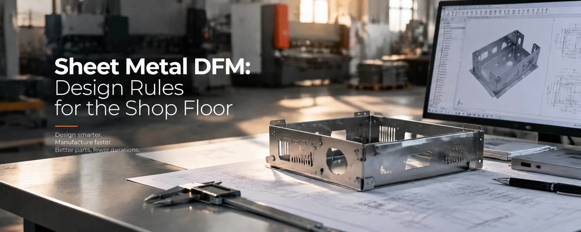
Design for manufacturing for sheet metal means designing within what the process can repeatably hold: holes at least as large as the material thickness, internal corner radii of half the thickness, flanges long enough for the tooling, holes kept clear of bend lines, and tolerances no tighter than the feature needs.
01What does the WERIX DFM review check?
When an RFQ arrives, an engineer reads it against the list below before pricing it. Where something will cause a manufacturability problem or an avoidable cost, it comes back as an observation with a suggested change — and the price reflects the corrected version, so you can see the difference.
| Feature | Rule of thumb | Why |
|---|---|---|
| Internal corner radius | At least half the material thickness | A round tool cannot cut a sharp internal corner |
| Hole diameter | At least the material thickness | Smaller holes need a secondary operation or a punch |
| Hole to bend line | At least 2.5 × thickness + inside radius | Holes inside the deformation zone distort |
| Minimum flange length | Several times the thickness, set by the V-die | A short flange cannot be supported during the stroke |
| Bend radius | At or above the minimum for the material and temper | Under-radius bends crack, especially across the grain |
| Slot width | At least the material thickness | Narrower slots cut badly and wear tooling |
| Edge distance to holes | At least the material thickness | Thin webs tear during forming and handling |
| General tolerance | ISO 2768-m unless a feature is functional | Tighter callouts add inspection, not accuracy |
| Counterbore / countersink | Only where the fastener requires it | Each adds an operation |
| Hardware inserts | Respect minimum thickness and edge distance | An insert needs material to displace into |
| Deburr note | Specify the edge condition you need | "Deburr all edges" on a 200-hole panel is a manual job |
| Finish | Standard colours and one finish per part family | Each colour or process is its own batch |
02Why does thickness come first in DFM?
Thickness is the most consequential single number on a sheet metal drawing. It sets the minimum hole size, the internal corner radius, the minimum flange, the bend radius, the required bend force and the achievable tolerance. Increase it by 50% and every one of those constraints tightens.
This is why "make it thicker so it is stronger" is such an expensive instinct. A stiffener, a formed rib or a change of section often delivers the stiffness at a fraction of the cost of moving to the next sheet thickness — and it stiffens the part without moving every other design constraint with it.
03Why is tolerance realism the biggest cost lever?
General tolerancing under ISO 2768-m covers the overwhelming majority of sheet metal features and costs nothing extra to hold. A drawing that nominates ±0.05 mm on every dimension is asking for a process the material cannot deliver, and the result is not a more accurate part — it is more measurement, more rejection and a higher price.
The practical approach is to tolerance by function: identify the features that locate, seal, mate or carry load, give those an informed callout, and leave the rest under general tolerance. That single change routinely removes a range of cost from a part without changing how it works.
04Should you design the assembly, not just the part?
A part that is manufacturable can still be an unassemblable product. Inserts that need press access from a side that will be closed later, welds on the inside of a sealed box, fasteners whose heads end up inside a cavity, and stacking tolerances across four mating parts are all assembly problems that surface late and cost disproportionately.
The fix is to design the sequence rather than the object: decide the order of join, then check that every fastening operation has tool access at the moment it happens.
- Confirm every fastener has tool access in the assembly sequence.
- Place welds where they can be reached and cleaned, and say whether they are structural or cosmetic.
- Do not stack tight tolerances across many parts — allocate them to the features that matter.
- Plan for the finish: masked threads, conductive contact areas and grounding points all need to be stated.
Frequently asked questions
Do you charge for a DFM review?
No. Manufacturability review is part of quoting. We read the drawing, flag anything that will cause a problem or an avoidable cost, and price the version we would actually make.
What is the most common DFM problem you see?
Short flanges and holes too close to bend lines — both are invisible in a 3D model and both force extra tooling or a relief. Tolerance over-specification is a close second: a drawing asking for ±0.05 mm generally across a laser-cut, bent part.
How thick can a formed sheet metal part be?
Our press brakes form mild steel up to around 5 mm, stainless to roughly 3 mm and aluminium to about 5 mm, subject to the inside radius and the flange length the tooling can support. Above that, other processes are usually more appropriate.
Can a sharp internal corner be laser cut?
No. The kerf is 0.1–0.5 mm wide and the beam is round, so every internal corner carries a radius of at least about half the kerf. Specify a slightly larger radius and it costs nothing.
Is ISO 2768-m good enough for sheet metal?
For the majority of features, yes. It covers general dimensions and angles under one callout and keeps the drawing clean. Reserve explicit tolerances for features that actually locate, seal or carry load.
Send the drawing, get a real answer
An engineer reviews your model for manufacturability and returns a costed quotation — with the DFM observations that would change the price.