
Bend Allowance Formula: Flat Pattern Length
The bend allowance formula is short, and almost every flat-pattern error comes from applying it with the wrong inputs rather than from the arithmetic. The angle must be in radians, the radius must be the inside one, and the K-factor has to match how the part will actually be formed.
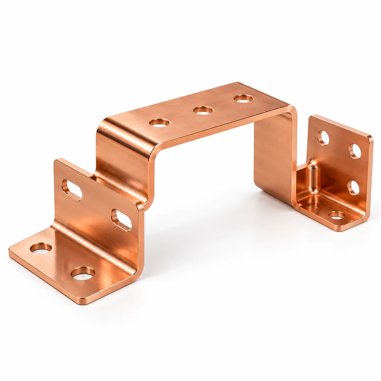
Bend allowance is the arc length of the neutral axis through the bend: BA = θ × (R + K × T), where θ is the bend angle in radians, R the inside radius, K the K-factor and T the thickness. Add it to the flat legs and you have the blank length.
10 rows of reference data below — the summary above is the short answer, the tables are what you quote from.
The formula, and what each term is
The formula is BA = θ × (R + K × T). The term (R + K × T) is the radius of the neutral axis: the inside radius plus the K-factor fraction of the thickness. Multiplying by the angle in radians gives the arc length along that neutral line, which is the amount of material the bend actually consumes.
| Term | Meaning | Common mistake |
|---|---|---|
| θ (theta) | Bend angle in radians (180° = π) | Using degrees — everything comes out wrong by a factor of 57.3 |
| R | Inside bend radius | Using the outside radius, which adds a full thickness |
| K | K-factor — neutral axis position as a fraction of thickness | Using a generic 0.33 for every radius and process |
| T | Material thickness | Using nominal thickness when the actual stock is at a tolerance limit |
| BA | Bend allowance — the arc length to be added | Adding it when the convention in use is bend deduction, which subtracts |
A worked example
Take a 90° bend in 2 mm cold-rolled steel with a 2 mm inside radius and a K-factor of 0.44 (a reasonable value at that radius-to-thickness ratio).
| Step | Value |
|---|---|
| Bend angle in radians | 90° × π / 180 = 1.571 rad |
| Neutral axis radius | R + K × T = 2 + (0.44 × 2) = 2.88 mm |
| Bend allowance | 1.571 × 2.88 = 4.52 mm |
| Flat legs (example) | 40 mm + 25 mm = 65 mm |
| Blank length (BA method) | 65 + 4.52 = 69.52 mm |
Bend allowance versus bend deduction
Both describe the same geometry and they are not interchangeable. Bend allowance adds the arc to the flat legs. Bend deduction starts from the sum of the outside dimensions — which is always longer than the blank — and subtracts the excess.
The relationship is straightforward: bend deduction equals twice the outside setback minus the bend allowance, where outside setback is (R + T) × tan(θ/2). A CAD system uses one convention internally, and a press-brake controller may use the other. Mixing them inside one flat pattern produces small errors per bend that accumulate across the part, which is why the convention belongs on the drawing or in the flat-pattern data.
Where flat patterns actually go wrong
- The bend angle was entered in degrees — the single most common error, and the most catastrophic.The outside radius was used in place of the inside radius, making every bend a thickness too long.A single K-factor was applied across a part with mixed radii, where the ratio differs enough to matter.
- The flat legs were dimensioned to the outside of the material but treated as neutral-axis lengths.The material thinned at a coined or bottomed bend, which a K-factor derived from air bending does not describe.Two bends meeting at a corner were treated as independent when the material between them shares strain.
How to verify a calculated value
Cut one blank to the calculated length, form it on the intended tooling, and measure a dimension that spans a bend. If the part is uniformly short or long, the K-factor is wrong and the correction applies to every bend. If one bend is out while the others are correct, the radius assumption on that feature is wrong.
For a prototype this check is enough. For production, arriving at the value once and locking the flat pattern is cheaper than discovering the drift across a batch — and it takes one part and a few minutes of measuring time.
Frequently asked questions
What is the bend allowance formula?
BA = θ × (R + K × T), where θ is the bend angle in radians, R the inside radius, K the K-factor and T the material thickness. It gives the arc length of the neutral axis, which is the material the bend consumes.
Should I use bend allowance or bend deduction?
Either, consistently. Bend allowance adds the arc to the flat legs; bend deduction subtracts the excess from the outside dimensions. The error comes from mixing the two inside one flat pattern, not from choosing one.
Why did my blank come out too short?
Almost always because the angle was entered in degrees instead of radians, or because the outside radius was used instead of the inside radius. Check those two first — between them they account for most flat-pattern errors.
Does the bend allowance change with material?
It changes mainly through the K-factor, which varies with the radius-to-thickness ratio and the forming method more than with the alloy. Two materials formed on the same tooling at the same radius behave similarly; the same material formed by coining versus air bending does not.
Is there a calculator for this?
Yes — the bend allowance calculator on this site takes thickness, inside radius, angle and K-factor and returns the neutral-axis length, using the same air-bending K table our press brakes are set up with.
Send the drawing, get a real answer
An engineer reviews your model for manufacturability and returns a costed quotation — with the DFM observations that would change the price.