
Progressive Die Design: Strip Layout and Stations
A progressive die is a sequence of operations arranged along a strip of metal that advances one pitch at a time. The part is never removed until the last station. Almost every decision that makes a progressive die cheap or expensive is made on the strip layout drawing, before a single die plate is cut.
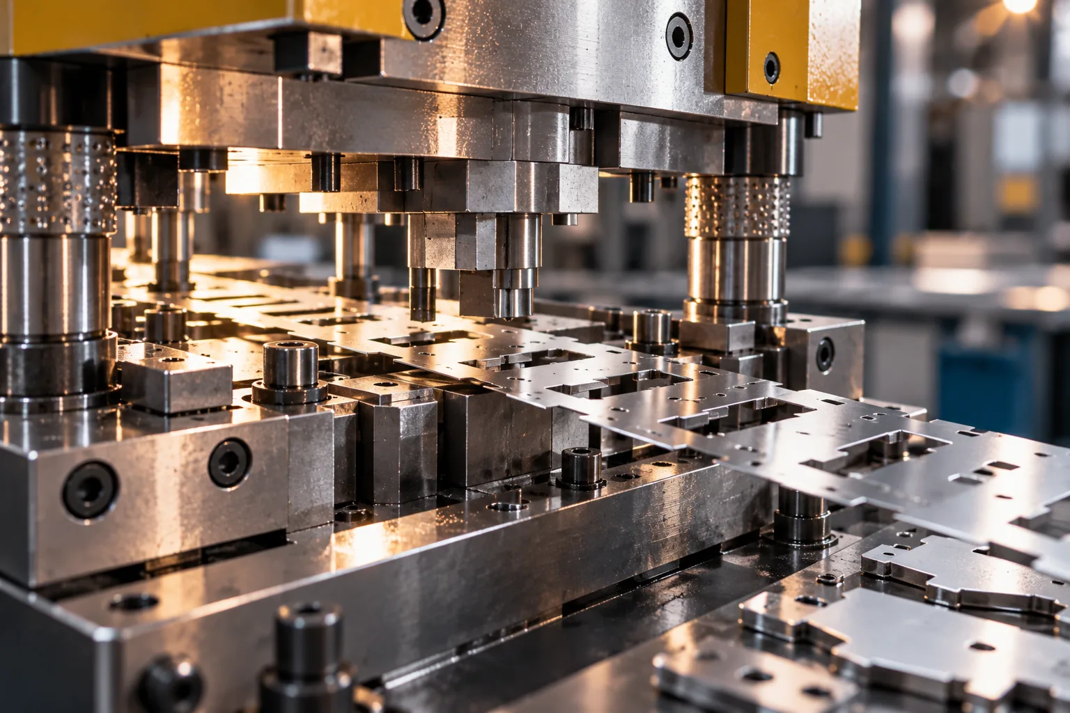
Progressive die design starts with the strip layout, not the part. The layout decides how many stations the part needs, how the material is carried between them, where pilots locate it and where a bend can be formed — and those decisions set both the die cost and whether the part can be made repeatably.
What the strip layout actually decides
The strip layout determines the pitch (how far the strip advances per stroke), the number and order of stations, where the carrier webs run, where pilots engage the material and where the part is finally cut free. Change the layout and the part may still be identical on the drawing while the die cost changes substantially.
This is why a die estimate issued before the strip layout exists is a guess. Two suppliers can quote the same part very differently because one sees a three-station layout and the other sees five — and both are describing the same geometry.
Carrier webs: how the part is carried
- Outer carrier (both sides)
- Two webs run along the strip edges, part held from outside · Most rigid and simplest to pilot; uses more material
- Single-side carrier
- One web down one side only · Less material; limited on parts with features near the free edge
- Centre carrier
- Web runs through a central zone inside the part · Good material use; needs a pierce-and-repierce step or leaves a bridge to remove
- None (cut-free / drop-through)
- Part fully separated, moved by gravity or air between dies · Cheapest layout, but only suits simple flat parts at high volume
Station sequence
Piercing usually comes first because everything downstream locates from those holes. Forming follows, and the order of forming operations matters: a bend that would obstruct a punch in a later station has to be performed later. Trimming and parting come last, so the strip stays intact as long as possible.
Where a part needs several bends in different directions, the sequence has to allow each bend to be formed without the part being trapped by a previously formed feature. That constraint is often what pushes a two-station layout into three, and it is the single most common reason a die estimate rises after the layout is drawn.
Pilots, bridges and bend relief
- Pilots locate the strip precisely at each station; they are usually formed from pierced holes in a prior station, so pilot holes must be pierced early and must be strong enough not to tear.Bridges are the small areas left between adjacent parts so the strip can carry them; too narrow and the strip distorts, too wide and material use suffers.
- Bend relief — a notch at the end of a bend line — prevents the material from tearing at the edge where a flange meets the side wall. Its absence is a common cause of cracked flanges discovered only at tryout.Strip distortion compounds: a forming station that pulls the strip out of position makes every later station inaccurate, so layout stiffness is chosen against the heaviest forming operation, not the first one.
Slug and scrap evacuation
Every pierce produces a slug, and a slug that does not clear will eventually be stamped into a part or jam the die. Layout design includes deciding whether slugs fall through the die, are blown out with air, or are pushed back up through the punch — and each choice affects die structure and cost.
Scrap removal is also a strip-layout decision. A layout that produces a single connected skeleton is easier to handle than one that produces many loose pieces, and the difference shows up in operator time and in the risk of a fragment reaching a part.
Design rules that keep a die alive
- Keep hole diameters at or above the material thickness where possible; smaller holes break punches.Space holes and blanks at least the material thickness apart so the web does not distort or tear.Give every internal corner a radius, and give the blank edge a radius rather than a sharp corner.
- Keep formed features clear of the carrier web so the strip is not pulled during forming.Design bend relief into any bend that runs into a wall; do not rely on tryout to add it later.Confirm the pitch and strip width against available die-set sizes before committing to a layout; a layout that needs a special die set costs more than one that fits a standard.
Frequently asked questions
Why is the strip layout the first drawing?
Because it fixes station count, pitch, carrier webs and pilot positions, and those determine the die structure and therefore most of the tooling cost. Estimating a progressive die before the layout exists means estimating the part twice.
How many stations does a progressive die need?
As few as the part allows and as many as the geometry demands. A simple pierced bracket can run in three; a part with several bends in different directions may need six or more, because each bend has to be formed in an order that does not trap the part.
What is bend relief and why does it matter?
It is a small notch cut at the end of a bend line where a flange meets a wall. Without it, the material tears at the transition under the forming stress. Adding it at design stage costs nothing; finding the crack at tryout costs a die modification.
Is a progressive die always the cheapest high-volume option?
For small, flat-ish parts at high volume, usually yes. For large parts that cannot be carried on a strip, a transfer die is the answer instead — it carries the part between stations rather than the strip carrying it, at the cost of a slower cycle.
Can a progressive die be modified later?
Yes, within limits. Adding a station or repositioning a feature is normal engineering. Changing the carrier type or the fundamental pitch is close to a new die, which is why the layout is worth reviewing with the customer before cutting starts.
Send the drawing, get a real answer
An engineer reviews your model for manufacturability and returns a costed quotation — with the DFM observations that would change the price.