
Sheet Metal Design Guide: Thickness to Fasteners
This guide follows the order we would actually design in: pick the thickness, then the material, then the geometry, then the fastening, then the finish. Get those in that order and the part is manufacturable almost by construction. Get them in the wrong order and every later decision fights an earlier one.
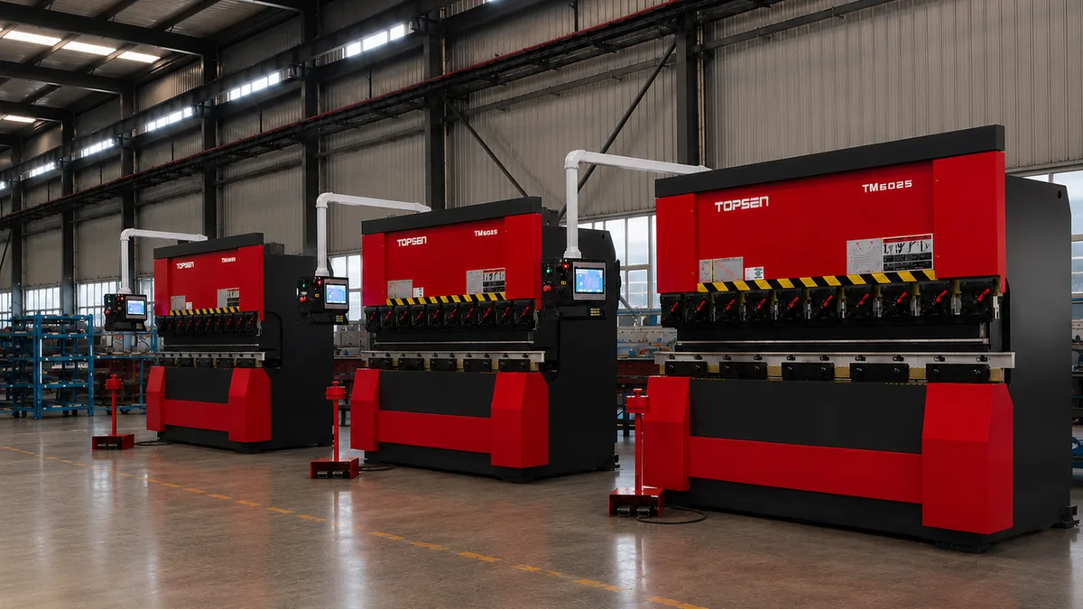
A sound sheet metal design starts from thickness, then builds the geometry around it: bend radii at or above the material minimum, flanges long enough for the tooling, holes clear of bend zones, hardware placed where it can be pressed, and a finish chosen for the environment rather than applied at the end.
01Step 1 — Thickness
Thickness is the root decision. It sets the minimum hole size, the minimum internal radius, the minimum flange, the bend radius available, the required press tonnage and the tolerance the process can hold. Because it constrains everything downstream, it is also the decision most often made casually and most expensive to revisit.
Choose the thinnest section that meets the structural and durability requirement, then add stiffness with geometry rather than mass. A formed rib, a hem, a returned flange or a change of section typically adds more stiffness per gram than moving up a thickness — and it does not tighten every other design constraint.
02Step 2 — Material
Material is chosen for the environment and the forming it has to survive, in that order. Corrosive exposure, food contact, weight budgets, thermal cycling, weldability and finish compatibility each eliminate options before cost is even considered.
The common stock we form from daily spans cold-rolled steel (SPCC), zinc-coated grades (SGCC, SECC), 304 and 316/316L stainless, 5052 and 6061 aluminium, and copper and brass for electrical and decorative parts. Each has a formability personality worth knowing: 5052 bends far more forgivingly than 6061, and austenitic stainless work-hardens as it forms.
03Step 3 — Geometry
- Design every internal corner with a radius of at least half the material thickness.Keep hole diameters at or above the material thickness; go up for tapped holes.Place holes at least 2.5 × thickness plus the inside radius away from a bend line, or add a relief.Keep flanges long enough for the V-die; short flanges cost a tooling change.
- Standardise on one inside bend radius across the part to avoid extra tooling setups.Avoid closed box sections you still need to weld inside; leave access for the torch.Give large unsupported panels a stiffening form — a rib, a step or a hem — rather than more thickness.
04Step 4 — Fastening and joining
How a part joins to its neighbours is a design decision with a manufacturing cost attached. Welding is strong and permanent but adds heat and distortion; self-clinching inserts give a machine thread in thin sheet but need minimum thickness, edge distance and press access; riveting suits mixed materials; and removable fasteners are cheaper to design in than to retrofit.
Two traps recur. The first is an insert placed inside a cavity that is welded shut after assembly — there is no press access, so the design has to change. The second is a weld specified without saying whether it is structural or cosmetic; those are very different joints at very different costs.
05Step 5 — Finish and edge condition
Finishes are chosen for function first: salt-spray exposure, abrasion, electrical conductivity, colour matching and appearance in that order. Powder coating suits durable colour on steel; anodising converts an aluminium surface rather than coating it; zinc and nickel plating protect steel with different appearance and cost profiles; brushing and sandblasting are mechanical finishes that read differently on different alloys.
Plan the masking at design stage. Threads, grounding points, conductive contact areas, and surfaces that must remain dimensionally accurate after coating all need to be identified — otherwise they are discovered as non-conformances.
06Which design review saves the most money?
The highest-return moment in any sheet metal project is the review between final CAD and tooling commitment. At that point a manufacturability observation costs nothing; three weeks later the same observation costs a die modification, a resubmission and a schedule slip. Send the model and the drawing for a DFM review before the design is frozen rather than after.
Frequently asked questions
Should I use 1.5 mm or 2 mm steel?
Choose from the duty, then check the constraints. Moving from 1.5 to 2 mm raises the minimum hole size, the minimum internal radius, the minimum flange and the bend force simultaneously. If the reason for the increase is stiffness, a formed rib is often the cheaper answer.
What is the best material for an outdoor enclosure?
For long exposure, 304 or 316 stainless, or steel with a proper protective coating. Zinc-coated steel with powder coating is the usual cost-effective answer; 316 is reserved for marine or chemically aggressive environments where the premium is justified by service life.
How do I design a part for powder coating?
Give every area you do not want coated a place to be masked, allow rack contact points you can accept showing witness marks, and remember that coating adds thickness to every surface in line of sight. Tell us which threads and contact surfaces must stay conductive.
Can I mix materials in one assembly?
Yes, but manage the consequences. Different materials expand at different rates, and dissimilar metals in a wet environment form a galvanic couple. Where both are unavoidable, use a barrier, a coating or an insulating washer, and say so on the drawing.
When should I stop designing and get a DFM review?
Before you freeze the design, not after the first article. A review on a near-final model catches the expensive issues — short flanges, misplaced holes, unreachable welds, over-tight tolerances — while they are still a five-minute change.
Send the drawing, get a real answer
An engineer reviews your model for manufacturability and returns a costed quotation — with the DFM observations that would change the price.