
Sheet Metal Tolerances: What Each Process Holds
A tolerance is a promise about what the process will repeat, not a wish about what the part should be. Sheet metal is a formed and stretched material, so its tolerances behave differently from a machined part — and drawings that ignore that difference get expensive without getting accurate.
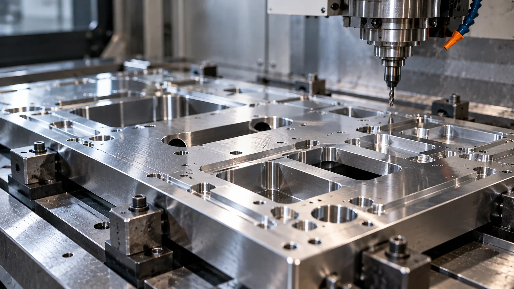
Sheet metal tolerances vary by process: laser cutting holds roughly ±0.1 mm on cut profiles, CNC bending holds about ±0.5° on bend angle, and flange positions accumulate along the bend sequence. General dimensions are normally covered by ISO 2768-m, with explicit callouts reserved for functional features.
01What tolerances does each process hold?
| Feature | Routine capability | Notes |
|---|---|---|
| Laser cut profile | ±0.1 mm | Within the normal material and thickness window |
| Punched features | ±0.1 mm | Depends on the tool and the punch/die clearance |
| Bend angle | ±0.5° | CNC press brake; ram positioning ±0.02 mm |
| Bend position / flange length | ±0.2 – 0.5 mm | Accumulates along the bend sequence |
| Hole position, non-critical | General tolerance | Covered by ISO 2768-m |
| Hole to bend proximity | 2.5 × t + inside radius minimum | Closer, and the hole distorts |
| Weldment overall | ±0.5 – 1 mm | Distortion from heat, controlled but not eliminated |
| Flatness, formed panel | Depends on size, thickness and finish | Coating adds stress; agree before finishing |
| General dimensions | ISO 2768-m (class m) | The default unless the drawing says otherwise |
Routine sheet metal process capability
02Why do bent parts accumulate tolerance?
A laser-cut blank holds its dimensions well because nothing moves. Bending is different: each bend stretches and compresses material, and the position of every subsequent feature depends on the accuracy of the bends before it. A part with six bends can be inside tolerance at every individual bend and still be out at the last hole.
This is why flange position tolerances are quoted relative to the datum a bend actually references, and why the fix for a part that drifts is usually to nominate a datum explicitly rather than to tighten every callout. It is also why the flat pattern must be built from the tooling and the K-factor the shop uses, not from a generic table.
03What is ISO 2768-m, and when should you specify tighter?
ISO 2768-m general tolerances bundle linear and angular tolerances under one callout. For a sheet metal part they cover holes that simply need to exist, edges that need to line up, and cosmetic features — the majority of the drawing.
Tighten only where a feature does something: a hole that locates a PEM insert, a mating face, a mounting pattern that must match a purchased component, a sealing surface. Indicating those explicitly, and leaving the rest under general tolerance, gives the shop a clear priority list instead of a uniform demand it cannot meet anyway.
- One general tolerance callout on the drawing, with explicit callouts only on functional features.
- Nominate the datum a critical dimension is measured from; do not leave it to interpretation.
- Accept that heat from welding moves material; specify the post-weld dimension, not the pre-weld one.
- Remember finishing adds thickness and stress — a coated dimension differs from a bare one.
04How do you measure what you actually specified?
Tolerances are only meaningful if they are verifiable. Every inspection activity has a cost and a lead time, so the inspection plan is agreed with the quotation: sampling and gauges for production, a full dimensional first article on a new tool or programme, CMM reporting where a customer specification requires it.
Where a drawing specifies a tolerance tighter than the process can repeat, the honest answer is that the parts will be inspected to that tolerance and rejected at that rate. Adjusting the callout is almost always cheaper than paying to discover the limit.
Frequently asked questions
What tolerance should I put on a sheet metal drawing?
ISO 2768-m general tolerances as the default, with explicit callouts only on locational, sealing or load-bearing features. That gives the shop a realistic target and keeps inspection effort where it produces value.
How accurate is laser cutting?
We hold ±0.1 mm on cut profiles within the normal material and thickness window. Corner radii and hole sizes follow from the kerf, and the process is repeatable within that band.
How accurate is CNC bending?
Roughly ±0.5° on bend angle in routine production, with ram positioning held to ±0.02 mm. Flange position is a separate tolerance and accumulates along the bend sequence.
Why does my welded assembly not hold its dimensions?
Heat input distorts metal. Even with controlled sequence and fixturing, a welded assembly holds a wider band than the same parts before welding. Specify the post-weld dimension and, where it matters, add a post-weld machining or adjustment step.
Does the finish change the tolerance?
Yes, measurably. Powder coating, anodising and plating all add thickness — anodising in particular is a conversion layer that grows both inward and outward. Where a coated dimension matters, specify whether the tolerance applies to the bare or the finished part.
Send the drawing, get a real answer
An engineer reviews your model for manufacturability and returns a costed quotation — with the DFM observations that would change the price.