
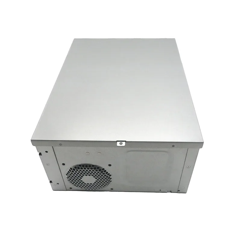
The assembly
A rectangular chassis roughly 600 × 400 × 150 mm built from 1.5 mm SPCC steel: a base pan, two side walls, two end plates and an internal divider. Joined by TIG on the outside corners with the visible faces dressed. Flat pack to the customer, assembled by us.
The functional requirement was that the mounting feet should sit in one plane and that the two side walls should be parallel within 0.5 mm over the full length, because the slide-in module that mounts inside is made to a fixed width.
Where the tolerance went
Individually, every part was inside its drawing tolerance. Clamped by hand and tacked, the assembly came out with walls that were parallel at the ends and pinched in the middle, and a base that had bowed between the feet. The error was small — under a millimetre — and entirely the result of weld shrinkage acting on an unsupported panel.
Two further effects compounded it. Tack-welding in one pass and finishing the weld later meant the assembly had already moved before the final weld locked it in. And because the side walls were clamped to the base rather than to each other, the base flatness error transferred into the wall spacing.
The fixes, in the order they were applied
| Change | Reason |
|---|---|
| Added two datum holes pierced in the base pan at the laser stage | Gives the jig one unambiguous reference instead of relying on edges |
| Built a fixture locating on those datums and clamping the walls to each other | Stops base flatness error transferring into wall spacing |
| Changed the sequence to complete the weld in one heat, alternating sides | Reduces the total heat input and balances shrinkage across the part |
| Added a temporary brace across the open top, removed after cooling | Holds the critical dimension while the material is hottest and weakest |
| Moved dressing to after the assembly cooled fully | Grinding a hot weld relieves stress and re-distorts what was straight |
Inspection
The inspection plan checks the datums first, then the features measured from them, then the assembly as a whole. Wall parallelism is measured at three positions along the length rather than one, because a single measurement would have passed the pinched assembly that started this work.
A first-article dimensional report is issued against the ballooned assembly drawing for the first unit and after any change to the sequence or the fixture. That is the point at which a jig problem is still cheap to fix.
What transfers
- On welded assemblies, design the datums into the parts at the cutting stage; a datum invented at assembly is a datum that moves.
- Sequence is a specification. Two shops can weld the same parts to the same drawing and produce different assemblies.
- Distortion control beats distortion correction — a jig costs less than dressing and re-straightening every unit.
- Name the critical assembly dimension on the drawing. If it is not named, nobody is holding it.