
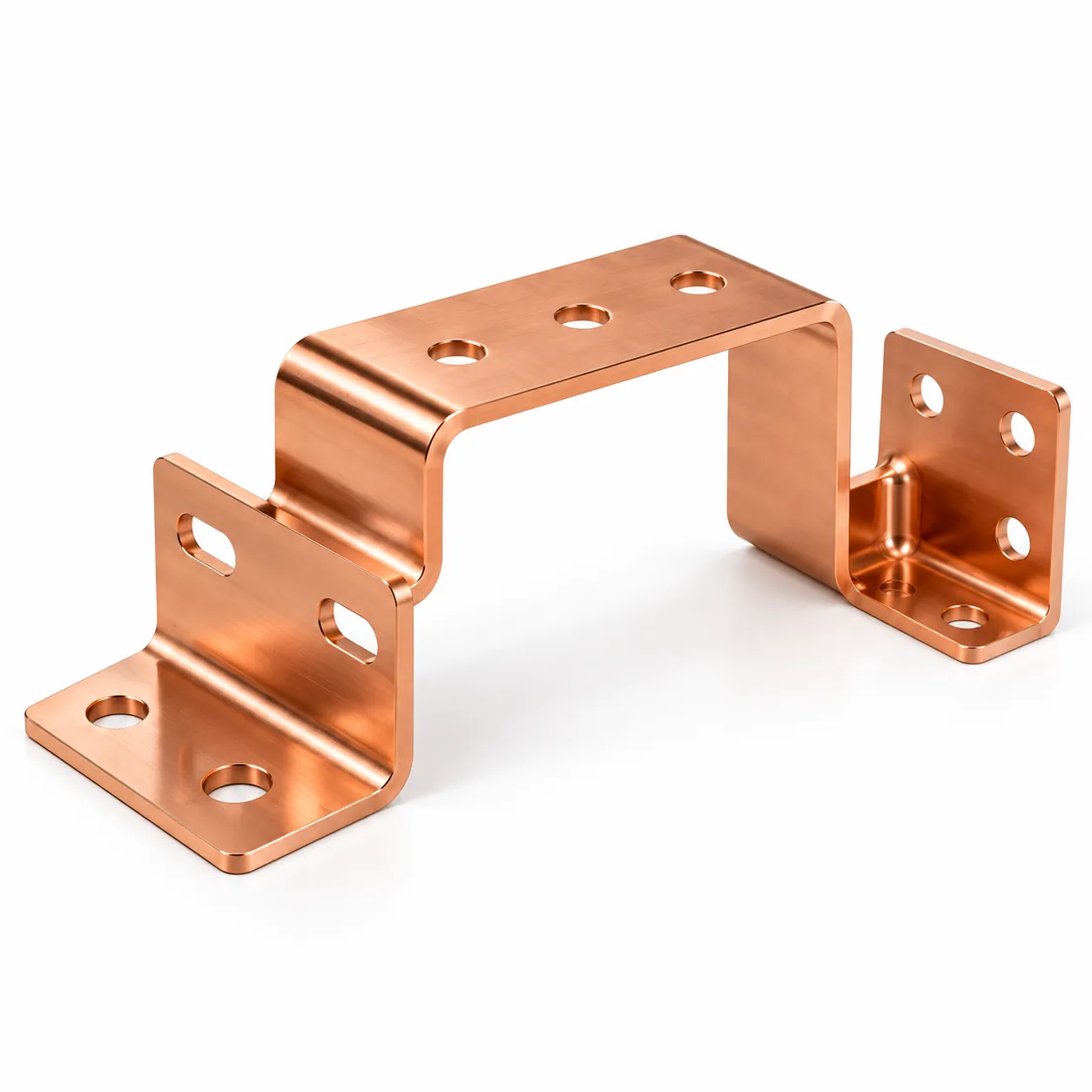
The part
Material: C11000 ETP copper at 3 mm, chosen for conductivity rather than for mechanical properties. A bracket that supports and positions two busbars, with a formed step to clear an adjacent component and two connection faces that carry current.
The drawing specified a 1 mm inside radius to match the steel bracket it replaced. That radius is achievable in mild steel at 3 mm and is not achievable in copper once the material has been work-hardened by a previous operation.
Why the radius had to change
Copper in the annealed condition is extremely formable; the same copper after a shear, a pierce and one bend is not, because the deformation has already consumed much of its ductility. The failure appears as a crack starting at the outside of the second bend, often at the sheared edge, where a burr acts as a stress raiser.
The change was to increase the second bend radius and to specify deburring of the sheared edges before forming. Both are cheap at design stage. Discovering cracking at the press is not, because the parts have already consumed material and machine time.
Forming and surface treatment
The contact faces are the part of the design that is easy to get wrong. Plating a contact surface looks tidy and is electrically worse: the connection relies on bare metal contact, and a plated surface is a different material with different behaviour under clamp load. The drawing therefore defines which areas are masked, and inspection verifies that they are bare.
| Decision | Reason |
|---|---|
| Deburr sheared edges before forming | Removes the stress raiser where cracks initiate |
| Open the radius on subsequent bends | Accounts for work-hardening from earlier operations |
| Form before plating | Plating a formed part is normal; forming a plated part cracks the deposit |
| Mask the contact faces | A plated joint has higher resistance and can loosen; bare copper is the contact surface |
| Tin plate the remainder | Prevents the surface oxidation that raises resistance over time |
| Specify the grain of direction on bends | Bending across the rolling direction is where copper is least tolerant |
Inspection
Inspection covered the bend geometry, the absence of cracking at the formed edges, plated thickness on the plated areas, and — specifically — that the contact areas were bare copper with no coating carry-over. The last check is the one that matters electrically, and it is a visual check against a defined area rather than a dimensional one.
Because copper is a sourcing-sensitive material, material certificates tied to the heat number were supplied with the order, as they are for any part where the customer specifies the grade.
What transfers
- Do not copy a steel part's bend radii onto copper. Work-hardening changes the answer between the first bend and the second.
- Deburr before forming where the material is crack-sensitive; the burr is the crack starter.
- Define masked areas on the drawing. Contact surfaces have to stay bare and that is a design decision.
- Form first, plate second. Forming a plated part damages the deposit at every bend.