Copper Busbar Bracket
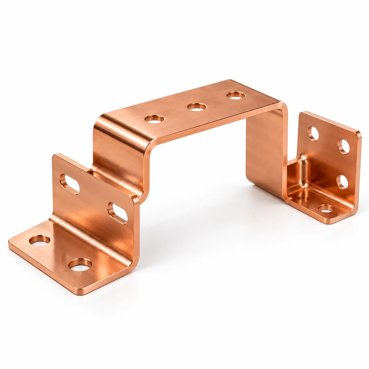
C11000 ETP copper bracket that supports and positions two busbars. The second bend radius is opened up to suit work-hardened copper, sheared edges are deburred before forming, and the current-carrying contact faces are masked so they stay bare metal. Made by WERIX Metal from C11000 ETP copper 3.0mm to a tolerance of ±0.1mm, finished with Tin plated, contact faces masked bare. Typical order volume is From 500 to 50,000+. Free DFM quote within 24 hours.
Copper Busbar Bracket
C11000 ETP copper bracket that supports and positions two busbars. The second bend radius is opened up to suit work-hardened copper, sheared edges are deburred before forming, and the current-carrying contact faces are masked so they stay bare metal.
| Part number | G-049 |
|---|---|
| Product type | Bracket |
| Industry | Power Grid |
| Material | C11000 ETP copper 3.0mm |
| Tolerance | ±0.1mm |
| Surface Finish | Tin plated, contact faces masked bare |
| Manufacturing processes | Laser Cutting · Deburring · CNC Bending · Tin Plating |
| MOQ / Volume | From 500 to 50,000+ |
Copper Busbar Bracket: manufacturing notes
Copper Busbar Bracket has to survive its application, not just its inspection report. This page sets out how the part is actually made — the material decision, the forming sequence and the tolerance strategy — so a buyer or engineer can judge whether the specification matches the application before a drawing is even sent.
Why this part is made in copper and brass
Copper Busbar Bracket is specified in C11000 ETP copper 3.0mm. Copper and brass are specified when conductivity, shielding performance or a decorative finish is the driver rather than structural strength. Both are soft and ductile, so forming is easy but the parts need careful support during handling and finishing; brass is often left as brushed or plated metal rather than painted.
How the part is formed
The production route for this part is Laser Cutting, Deburring, CNC Bending, Tin Plating. Fiber laser cutting separates the blank without hard tooling, which is what makes a first article economical: the profile can change between the prototype and the production run without a die sunk. The trade-off is a small heat-affected edge, so on parts that will be painted we deburr and, where the edge is a sealing face, dress it flat before coating. Deburring is not cosmetic: a burr under a gasket becomes a leak path, and a burr inside an enclosure becomes a cable or insulation hazard. It is quoted as a process step so that it is planned and inspected rather than left to the end of the shift.
What ±0.1mm actually requires on the shop floor
The drawing calls for ±0.1mm. On a part like this that is a process decision, not an inspection decision: it fixes which machine holds the critical features, how the part is fixtured for each operation, and whether a formed feature can be checked after coating or has to be measured before it. We confirm the first article against the drawing and record the values, so the tolerance is demonstrated rather than assumed. If a dimension in your drawing is tighter than this part needs, it is usually worth relaxing it — over-toleranced features are one of the quietest cost drivers in a sheet metal quote.
Frequently asked questions
- What is the minimum order quantity for copper busbar bracket?
- The order range for this part is From 500 to 50,000+. Below the low end of that range the tooling and setup are spread over too few pieces to be economic, so if you are prototyping we would normally build the first units from the same process route and quote the production quantity separately.
- Can the material be changed to reduce cost or weight?
- Yes, and it is worth asking before the design is frozen. The current specification for this part is C11000 ETP copper 3.0mm; depending on the service environment, a different grade or a lighter gauge with formed stiffening can meet the same requirement. What we would not do is change the material without re-checking the bend radii, the welding process and the coating system, because all three move with the substrate.
- What finishing options are available for this part?
- The current finish specification is Tin plated, contact faces masked bare. Because every finishing line runs in-house, the finish can be changed without changing supplier, and we match colour to a RAL or Pantone reference on the drawing.
- How long does production take, and what do you need from us to quote?
- Prototypes are typically 3–7 business days and production runs 7–15 days once the drawing is released and the finish is confirmed. To quote we need the drawing or CAD file (STEP, DXF, DWG, IGES or PDF), the material and finish, the quantity and the destination — and any tolerance or inspection requirement that is not already on the drawing. You get a DFM review with the quotation, not after it.
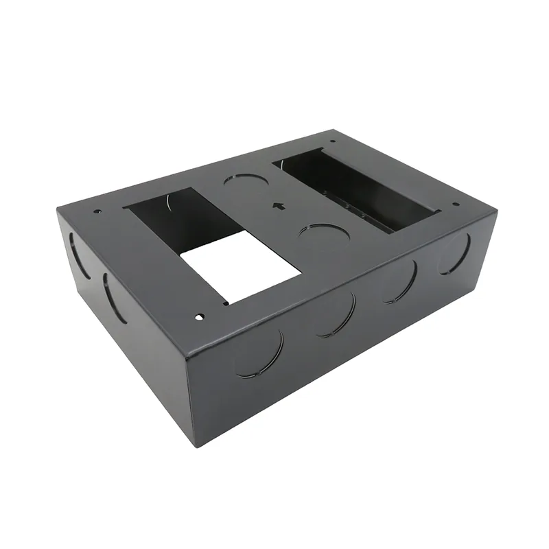
Sheet metal engineering guides
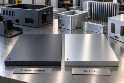 Powder Coating vs Anodizing: How to ChoosePowder wins on colour and substrate range; anodizing wins on wear and thinness. Five rules that decide it, with the cost drivers behind each.Read More
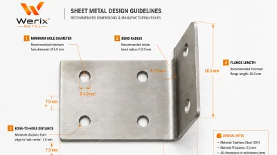 DFM for Sheet Metal: Essential Design Rules That Save Cost and Prevent Production FailuresDesign-for-manufacturing rules for sheet metal — minimum hole sizes, bend radii, edge distances, tab-and-slot design, and common mistakes that cause scrap.Read More