
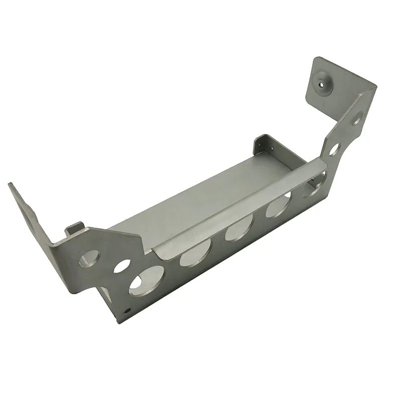
The part
| Item | Detail |
|---|---|
| Application | Structural mounting bracket inside a vehicle sub-assembly |
| Material | High-strength low-alloy steel strip, 2.0 mm |
| Prototype route | Fibre laser cut, CNC bent, deburred by hand |
| Production route | Progressive die, 6 stations, 160 t press |
| Features in the die | Blank, pierce, form, restrike, trim, separate |
| Secondary ops | Tumble deburr, then zinc-nickel plating |
| Tolerance | ±0.15 mm on the two locating holes; general tolerance elsewhere |
Why the process changed
The prototype route worked and the parts were correct — that was never the issue. The problem was that every bracket carried a full programme, a setup and a manual deburr, and at production volume those fixed costs dominated the price. On a part with two formed features and five pierced holes, a die pays back because every stroke delivers a finished part with no handling between operations.
The calculation that decided it was straightforward: the die cost divided by the saving per part against the laser route. On this part the saving per piece was large enough that the payback sat well inside the programme life.
Strip layout: the decisions that could not be revisited
The strip layout was signed off before any die steel was cut, because none of it can be changed afterwards. Three decisions were locked in at that point.
- Material width and progression pitch, which together set how much strip each part consumes regardless of part area.
- Bridge strategy: how the part stays attached to the strip until the separation station, and where the material for each form comes from.
- Pilot hole position and size, so the strip is located from the first station onward and error does not accumulate along the progression.
- Bend relief and trim radii, because both affect die wear over the tool life.
- Burr direction, which is set by the punch-die clearance and therefore by which face the part is sheared against.
- On a high-strength material the forming stations do more work than on mild steel, so the strip had to carry the part through more stations before separation and the tonnage per station was higher. That is a strip decision, and getting it wrong would have meant a rebuilt die rather than an adjusted one.
Proving the die
The first article was run on the production die, not on a soft tool, and measured against every dimensioned feature on the drawing. Two of the five hole positions and one formed angle needed adjustment at try-out; the rest held comfortably, which is what the report is for.
The locating holes were measured as a pattern, because that is how the part is used. Hardness and plating thickness were recorded on the plated sample. The strip layout, the try-out adjustments and the final dimensions went into the tool record that travels with the die.
What we would do differently
Prototype on the laser route but to the die flat pattern. The prototype parts were made from a flat pattern calculated for bending, which is close to but not identical to the flat pattern the strip produces. Getting them onto the same development eliminated a small dimensional reconciliation at first article.