
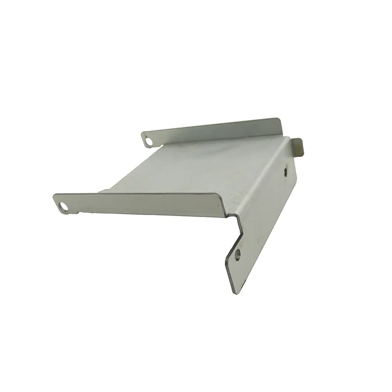
The part
Material: SGCC galvanised steel at 2 mm, chosen for stiffness in a gusseted form and for corrosion resistance in a workshop environment. A folded bracket roughly 300 × 200 mm per leg, with a gusset, mounting holes for a linear rail on one face and fixing holes to the printer chassis on another.
The requirement came from the customer's calibration procedure: the two rails had to be parallel within a tolerance that, if exceeded, showed up as layer shifting in the printed part. That is a system-level requirement landing on a sheet metal bracket.
Why hole position mattered more than stiffness
The bracket is stiff enough by any ordinary measure — it is a small gusseted part carrying a modest load. What it could not do was allow the rail mounting holes to be positioned loosely, because a hole position error rotates the rail, and a rotated rail produces a print defect measured in tenths of a millimetre across the build volume.
That flipped the normal design priorities. Instead of adding material for stiffness, the work went into datum strategy: positioning the rail holes from a pierced datum rather than from the folded edge, and matching the chassis holes to the same datum so the two interfaces relate directly to each other.
Forming and finish
| Decision | Reason |
|---|---|
| Gusset formed rather than welded | A formed gusset introduces no heat and therefore no distortion |
| Rail holes from a pierced datum | Removes dependence on the folded edge condition |
| Chassis holes from the same datum | Holds the relationship between the two interfaces directly |
| Bend angle called out separately | A 0.5° angular error over 300 mm is a visible position error at the rail |
| Zinc finish left as mill coating | No coating build on hole edges or mating faces |
Inspection
The first article measured hole positions from the datum, the angle between the two mounting faces, and the flatness of the rail mounting face. Hole position and face angle together determine whether the rail ends up parallel, so inspecting one without the other would not have demonstrated the requirement.
Because the customer's calibration catches residual error, the acceptance test is ultimately the printed part. Our position is to hold the bracket geometry that makes calibration achievable rather than to promise a print result, and stating that boundary is part of the engineering conversation.
What transfers
- On machine frames, hole position tolerance propagates into the machine's accuracy. Treat it as a machine specification.
- Position mating features from a pierced datum so two interfaces relate directly rather than through the part's outer form.
- Form gussets instead of welding them where distortion would be expensive to correct.
- State the boundary between what the bracket holds and what the customer's calibration finalises.