
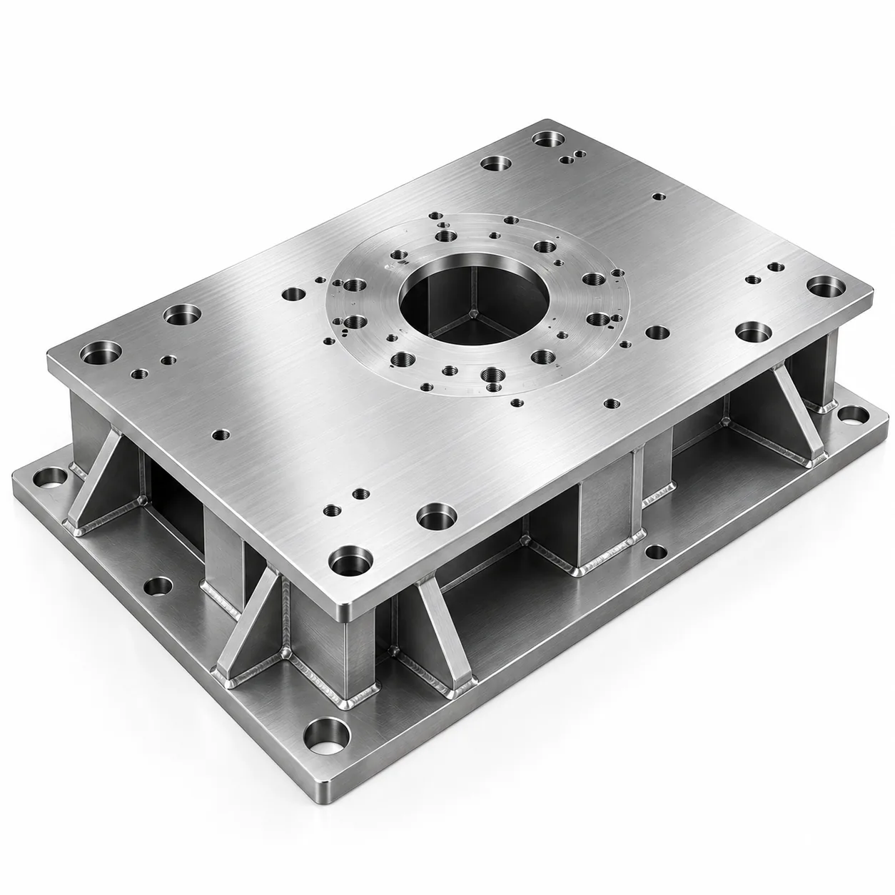
The part
A robot pedestal mounting plate, roughly 1,200 × 800 mm, fabricated from 8 mm base plate and 6 mm stiffening ribs in S355 structural steel, with a machined top interface for the robot base. The robot's repeatability depends on that interface being flat and on the bolt pattern being positioned accurately.
Two interfaces mattered: the robot mounting face, which is machined, and the floor interface, which is not, because the plate is grouted or shimmed on site.
Why welding could not solve flatness
Welding 6 mm ribs to an 8 mm plate puts a large amount of heat into a stiff assembly. The shrinkage pulls the plate into a dish, and the stiffer the ribbing the more the distortion is concentrated in the base plate rather than absorbed by the structure. Floor flatness here was outside acceptable limits by several millimetres, not tenths.
Straightening after welding — press work or local heating — introduces residual stress that later releases, and the release moves the interface after the robot is mounted. That is a failure mode that appears in service rather than at inspection, which is the worst kind.
The route change
The accepted route was the third: weld the plate with machining allowance on the interface, stress-relieve it, then machine the top face and the bolt pattern in one setup. Machining after relief removes the distortion and leaves no locked-in stress to release later.
| Route | Achievable flatness | Risk |
|---|---|---|
| Weld and use as welded | Millimetres out of flat | Robot bolted to a dished face; repeatability lost |
| Weld, straighten, use as straightened | Possible to reach tolerance | Residual stress releases in service and the interface moves |
| Weld oversize, stress-relieve, machine the interface | Achievable to a tight tolerance and stable | Adds a machining operation and a heat-treatment step |
| Weld, then shim on site | Depends on the installer | Puts a critical requirement outside the factory |
Datums and the fixture
The machined interface becomes the datum for everything else, so the sequence is: fabricate, relieve, machine the interface and the bolt pattern in one setup, then drill the floor fixing holes from the same datum. Drilling the floor holes before machining would have made them dependent on the distorted plate.
The welding fixture only had to hold the assembly within machining allowance rather than hold it flat, which is a much cheaper fixture. That is the practical benefit of routing the problem into machining: the fabrication stage gets easier, not harder.
Inspection
Flatness of the machined interface and position of the bolt pattern were measured after machining and recorded on the first article, together with the datum reference. Floor fixing hole positions were verified from the same datum so the relationship between the two interfaces is demonstrated rather than assumed.
A first-article report is issued for the first plate and after any change to the weld sequence, the heat treatment or the machining setup, because all three affect the result.
What transfers
- When a welded part needs a flat or precise interface, machine it after welding rather than trying to weld it flat.
- Stress relief removes the locked-in stress that would otherwise move the part in service.
- Establish the machined surface as the datum and drill everything else from it.
- A fixture that only has to preserve machining allowance is far cheaper than one that has to hold final flatness.