
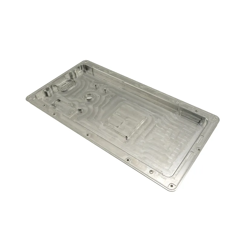
The part
Material: 5052 aluminium at 1.5 mm for the chassis body, with an aluminium front and rear panel. A bench-top instrument housing roughly 400 × 350 × 150 mm, with internal mounting for a power board, a control board and a sensor module, and a display aperture in the front panel.
The requirements that shaped the design were EMC shielding continuity across every panel joint, thermal contact between a power component and the chassis wall, and cleanable external surfaces for laboratory use.
Shielding continuity without a die
EMC shielding depends on a continuous conductive path around every joint. On a tooled enclosure this is often provided by a formed gasket channel or by dedicated spring fingers. At low volume, without a die, the practical approach is to design bare-metal contact lands into the formed panels and rely on fastener spacing to keep them closed.
The panel-to-panel flanges were therefore left unmasked and unpainted, and the fastener spacing was set to keep the flanges in contact between fasteners rather than only at them. That is the same principle as gasket compression: contact is only achieved where the parts are held together.
Thermal contact and cleanability
The component bracket that carries the hot part was formed as a flat pad that bolts against the chassis wall. Flatness mattered more than thickness: a bowed pad makes contact at two points and insulates everywhere else. Building it from 1.5 mm with a controlled flat pad was cheaper than using thicker material and still leaving a gap.
| Requirement | Solution |
|---|---|
| EMC shielding continuity | Bare-metal flanges at every joint, fastener spacing set to maintain contact |
| Thermal contact to chassis wall | Component bracket formed flat against the wall, flatness controlled on the first article |
| Cleanable external surfaces | Formed surfaces with no ledges; anodised rather than painted where a finish was required |
| Display aperture rigidity | Formed return around the aperture rather than a flat cut-out |
| Service access | Removable top cover and rear panel, both with gasket lands for shielding |
Inspection
Inspection covered the flatness of the thermal pad, continuity across the assembled chassis, and the dimensions of the display aperture. Continuity was measured on the assembled unit rather than on individual panels, because the property only exists once the panels are fastened together.
A first-article dimensional report was issued for the first unit, together with a continuity check recorded as a pass or fail rather than a dimension. That is the honest form for an electrical property on a mechanical assembly.
What transfers
- EMC continuity is a design feature: bare-metal lands and sensible fastener spacing, not a coating decision made at the end.
- Thermal contact needs flatness, not thickness. A flat 1.5 mm pad outperforms a bowed 3 mm one.
- Measure electrical properties on the assembled unit, because they only exist in the assembly.
- At low volume, geometry can substitute for tooling if the design is arranged to allow it.