
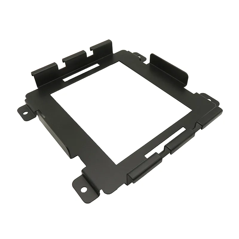
The part
| Item | Detail |
|---|---|
| Application | Floor-standing machine control cabinet, front and rear access |
| Shell | Cold-rolled steel 1.5 mm panels on a welded frame, 2.0 mm doors |
| Mounting plate | 2.5 mm steel, separate part number, drilled and tapped to layout |
| Gland plate | Removable, 2.0 mm, supplied blanked and drilled to schedule |
| Cut-outs | HMI aperture and device cut-outs in the front door |
| Finish | Powder coat inside and out, earth points and gland lands masked |
| Hardware | Hinges, quarter-turn locks, DIN rail, cable ducts, door earth strap |
Designing for revision
The shell depends on internal volume, mounting arrangement and environment — all known early. The mounting plate and the cut-outs depend on the electrical layout, which was still moving. Treating them as separate parts meant a late change re-cut a plate rather than a painted cabinet.
That split also made the cabinet reproducible. Two units built months apart share an identical shell and separately drilled plates, so a spare cabinet can be produced without reference to the electrical revision it happened to be built alongside.
Cut-outs and the datum problem
The original door drawing located the HMI aperture from the outside corner of the door, and the device cut-outs from the door centreline. Neither is a datum the process can hold: the outside corner accumulates the blank, bend and coating steps before it.
The revision dimensioned everything from the left-hand formed edge — a crease the press brake produces and which a CMM can find reliably. Device clearances were then verified on all four sides of every cut-out, not just the aperture size, because fixing clips take space that a cut-out schedule does not show.
- Cut-outs repositioned off the formed edge instead of the outer corner.
- Aperture tolerance split: ±0.3 mm on position, device clearance verified separately.
- Coating thickness allowed for in the aperture, so the device still fits after powder coating.
- Masking nominated for the door earth strap land and the gland plate face.
Assembly order, and the insert inside the closed box
The first layout placed two PEM studs on a bracket that ends up inside the closed frame, with no press access once the side panels are riveted. Rather than modify the cabinet, the studs were moved onto the mounting plate, which is drilled before assembly and installed last.
The sequence was then written down and walked through feature by feature: which inserts are pressed, which plates are drilled, which hardware is fitted, and in what order the panels close. That document is now part of the drawing package, which is a change we would keep for every cabinet of this type.
Inspection and hand-off
The aperture and cut-out positions were measured on the first article, and then checked on every unit with a simple check plate before coating — because a coating defect is recoverable and a mis-cut door is not. Earth continuity was verified after coating, on every cabinet.
Cabinets shipped with the mounting plate installed but undrilled where the layout was still open, with the drilling scheduled separately. That is a deliberate trade: it costs a second shipment of a small plate but removes the risk of a scrap cabinet from a late electrical change.