
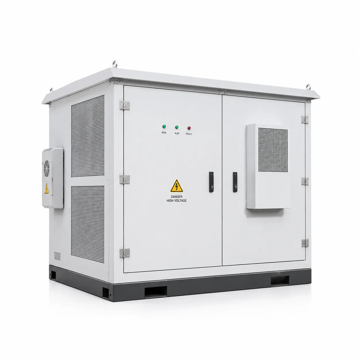
Earth continuity decides the material and the coating
A painted enclosure is an insulated enclosure. If the earth path runs through bolted flanges, studs or gland plates, every one of those contact surfaces has to stay bare metal — which means masking before coating, and a process that can mask accurately on a production part.
This is the single most common design omission in electrical enclosures: the label shows an earth stud, the drawing does not mask it, and the finished part arrives with no continuity between the stud and the body. Adding "mask earth stud and flange lands, coat thickness 60–120 µm elsewhere" to the drawing removes the whole problem.
- Nominate the earth points and sealing faces explicitly; they must be masked before coating.
- Powder coat is an insulator — do not assume a stud presses through it reliably.
- Galvanised steel gives a conductive surface without coating, which is why it dominates outdoor electrical work.
- Where stainless is used for corrosion rather than finish, an unpainted 304 body is often cheaper than a painted one with masked earth paths.
Cut-outs, gland plates and the tolerance stack
Devices are installed in a rectangular cut-out that is usually to a published standard, with tolerance that is a fraction of the clearance the device needs. The complication is that the cut-out sits at the end of a chain: flat blank, bend, weld, coat. Every step before the cut-out moves it a little.
Where a device position matters, the fix is to reference it to a datum the process can actually hold — usually a bend line or a formed edge — rather than to the far corner of the box, and to cut it after forming where the geometry allows.
| Environment | Typical material | Typical finish | Note |
|---|---|---|---|
| Dry indoor, plant room | Cold-rolled steel 1.2–1.5 mm | Powder coat, standard RAL | Mask earth studs; cheapest route |
| Indoor, humid or washdown | Galvanised steel, or 304 | Powder coat over galvanised / bare 304 | Galvanised under coating resists cut-edge rust |
| Outdoor, sheltered | Galvanised 1.5–2.0 mm | Powder coat, textured or smooth | Drainage and slope matter more than a thicker sheet |
| Outdoor, coastal or chemical | 316 / 316L | Bare, or anodise if aluminium | Plate or coat fixings too, or they become the corrosion site |
| Food or pharma adjacent | 304, crevice-free design | Bare, passivated | Avoid open seams and unsealed laminations |
Things that stop a panel fitting
A back plate drilled to a layout, a DIN rail whose position is called out from a different datum, and cable ducts that consume the width the devices needed — these are assembly problems, not fabrication problems, and they surface on the customer line rather than in our shop.
The fix costs nothing at design stage: draw the panel populated. Every device, every duct, every wire bend radius, every tool clearance. If the layout only fits in CAD when nothing is filled in, it will not fit on site.
- Draw the enclosure populated, including ducts and wire bend radii, before releasing the drawing.
- Give the door swing clearance: hardware, handles and hinges all consume radius.
- Screwed-on gland plates ship better than welded ones when the cable schedule is not final.
- Where a device is mounted to the door, remember the door is a separate part with its own thickness and tolerance.