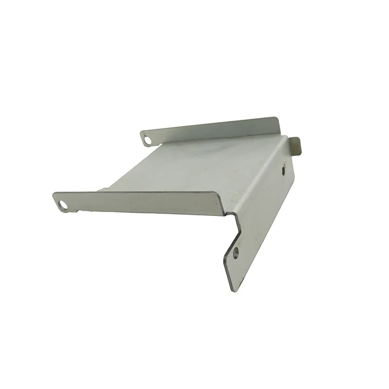
Linear Rail Mount
Precision mounting plates for linear guide rails machined to ±0.1mm for backlash-free axis motion. Critical for print quality — misalignment causes dimensional inaccuracy. Made by WERIX Metal from AL6061-T6 aluminum 5.0mm to a tolerance of ± 0.02 mm, finished with Anodizing Type II. Typical order volume is From 50 to 20,000+ volume. Free DFM quote within 24 hours.
Engineering drawing available on request
Send your target specifications — we reply with a drawing and a DFM quote within 24 hours.
Linear Rail Mount
Precision mounting plates for linear guide rails machined to ±0.1mm for backlash-free axis motion. Critical for print quality — misalignment causes dimensional inaccuracy.
| Part number | P-050 |
|---|---|
| Product type | bracket |
| Industry | 3D Printing |
| Material | AL6061-T6 aluminum 5.0mm |
| Tolerance | ± 0.02 mm |
| Surface Finish | Anodizing Type II |
| Manufacturing processes | CNC Milling · Drilling · Tapping |
| MOQ / Volume | From 50 to 20,000+ volume |
Linear Rail Mount: manufacturing notes
This part — linear rail mount — is manufactured in our Dongguan plant. The notes below explain the manufacturing decisions behind the specification: why this material, why this forming sequence, and what the tolerance actually requires in production.
Why this part is made in aluminium
Linear Rail Mount is specified in AL6061-T6 aluminum 5.0mm. Aluminium buys weight reduction and thermal conductivity, at the cost of stiffness: a section that is stiff enough in 1.5 mm steel needs either a thicker gauge or formed stiffeners in aluminium. It anodises rather than paints when a hard, non-flaking surface is wanted, and it needs dedicated tooling and fixturing because the soft surface marks easily during handling.
How the part is formed
The production route for this part is CNC Milling, Drilling, Tapping. Threads are either cut into the sheet or carried by an inserted fastener. Cut threads are cheaper and fine in thicker gauges; in thin sheet an inserted nut holds far more torque and can be replaced if a thread is stripped in service, so the joint’s future service life decides which one we specify.
What ± 0.02 mm actually requires on the shop floor
The drawing calls for ± 0.02 mm. On a part like this that is a process decision, not an inspection decision: it fixes which machine holds the critical features, how the part is fixtured for each operation, and whether a formed feature can be checked after coating or has to be measured before it. We confirm the first article against the drawing and record the values, so the tolerance is demonstrated rather than assumed. If a dimension in your drawing is tighter than this part needs, it is usually worth relaxing it — over-toleranced features are one of the quietest cost drivers in a sheet metal quote.
Finishing: anodising
Anodizing Type II. Anodising converts the aluminium surface into a hard oxide layer instead of adding a film, so it does not chip and flake the way a coating can. It is the reason aluminium parts often ship anodised rather than painted, and the layer thickness is chosen for the service — decorative, wear-resistant or hard-anodised for moving surfaces.
Frequently asked questions
- What is the minimum order quantity for linear rail mount?
- The order range for this part is From 50 to 20,000+ volume. Below the low end of that range the tooling and setup are spread over too few pieces to be economic, so if you are prototyping we would normally build the first units from the same process route and quote the production quantity separately.
- Can the material be changed to reduce cost or weight?
- Yes, and it is worth asking before the design is frozen. The current specification for this part is AL6061-T6 aluminum 5.0mm; depending on the service environment, a different grade or a lighter gauge with formed stiffening can meet the same requirement. What we would not do is change the material without re-checking the bend radii, the welding process and the coating system, because all three move with the substrate.
- What finishing options are available for this part?
- The current finish specification is Anodizing Type II. Powder coating, anodising, zinc or nickel plating, brushing and blasting are all available in-house, so the finish can be changed without changing supplier — and where the part will be seen, we match colour to the RAL or Pantone reference on your drawing.
- How long does production take, and what do you need from us to quote?
- Prototypes are typically 3–7 business days and production runs 7–15 days once the drawing is released and the finish is confirmed. To quote we need the drawing or CAD file (STEP, DXF, DWG, IGES or PDF), the material and finish, the quantity and the destination — and any tolerance or inspection requirement that is not already on the drawing. You get a DFM review with the quotation, not after it.
Sheet metal engineering guides
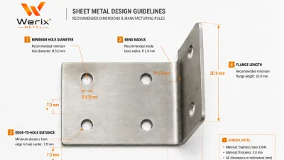 DFM for Sheet Metal: Essential Design Rules That Save Cost and Prevent Production FailuresDesign-for-manufacturing rules for sheet metal — minimum hole sizes, bend radii, edge distances, tab-and-slot design, and common mistakes that cause scrap.Read More
 Sheet Metal Fabrication vs CNC Machining: How to Choose the Right ProcessSheet metal fabrication and CNC machining serve different geometries, volumes, and budgets. This data-backed comparison covers cost, tolerance, materials, and lead time.Read More