
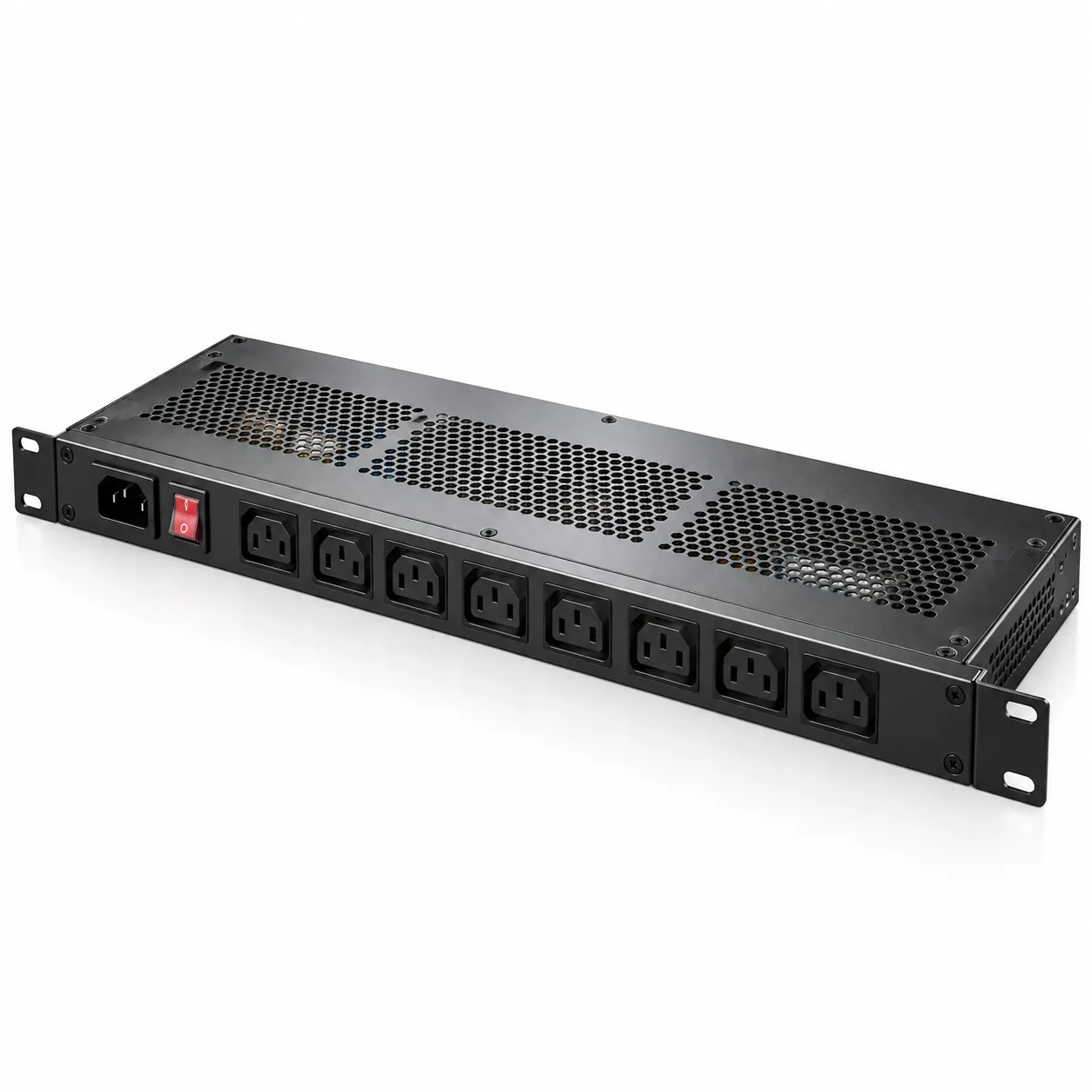
The part
| Item | Detail |
|---|---|
| Application | 1U rack-mount power distribution unit, 19-inch rack |
| Material | Cold-rolled steel (SPCC), 1.2 mm |
| Route | Fibre laser cut, CNC bent, spot welded at the flange returns |
| Ventilation | Perforated top panel to an agreed open-area figure |
| Finish | Powder coat, standard RAL, masked earth stud and rail contact lands |
| Interface | 19-inch front panel, EIA-310 rail spacing, rear cable entry |
| Secondary ops | PEM studs for the internal bracket, silk-screen marking on the front panel |
Three fixed dimensions and one flexible one
The rail spacing and the front panel width are standard, so they were the datum. The internal busbar was a purchased component with published clearances, so that set the internal height. The vent area was a thermal requirement, so that set the open proportion of the top panel. Depth was the only genuinely free dimension.
Designing in that order meant the front panel and the mounting holes were placed from the rack interface rather than from the tray corner, which is the difference between a unit that slides in and one that needs a persuasion tool. The tolerance stack ran from the mounting flange backwards, so the flange and its forming were the two features held tight.
Where the DFM conversation went
The first drawing showed a perforated top panel with a generous open area and no stiffening. A 1U tray with that much material removed twists when it is bolted into a rack, and the front panel then does not sit square in the aperture — a cosmetic and functional problem at the same time.
Two changes resolved it without reducing the open area. A shallow formed rib was pressed across the tray behind the front panel, and the side returns were extended so they carried load from the rail to the back of the unit. Both are forming operations in the same programme; neither added thickness or a part.
- The rib replaced a proposed increase from 1.2 mm to 1.5 mm, which would have changed rail loading and tooling.
- Perforation was laser cut rather than punched, because the pattern was still being agreed when the first units were needed.
- PEM studs were pressed before the top panel was spot welded on, because there is no press access afterwards.
Inspection and hand-off
The front panel mounting holes and the rail spacing were measured on the first article as a pattern, not as individual dimensions, because that is how they are used. Flatness of the tray was checked across its length with the unit assembled, since that is the condition that matters in the rack.
Units shipped assembled with the internal bracket studs in place and the front panel marked. Hardware was torqued and verified before packing rather than bagged loose, because a stud that backs out in transit becomes a short circuit rather than a missing part.