
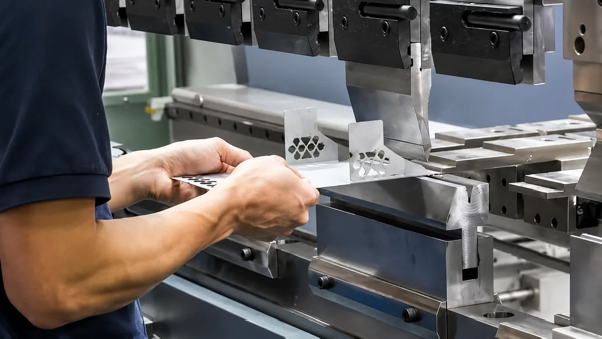
What Bend Line means
A bend line marks where the flat sheet enters the deformation zone of a bend. It is drawn on the flat pattern, programmed into the press brake as the back-gauge reference, and it is the line every proximity rule is measured against: hole clearances, flange lengths, relief placement and the minimum distance between two bends all resolve back to it.
Why it matters on the shop floor
What the drawing does not need is the bend line itself — CAD produces it when the flat is unfolded. What the drawing does need is everything that touches it kept at a safe distance. A hole edge inside the deformation zone goes oval; a flange shorter than the die cannot be formed; two bend lines too close fight over the same material. The bend line is where those decisions are visible.
What to remember
- Hole edge to bend line: roughly 2.5 × t + R as a working minimum.
- Between two parallel bends, leave room for the tooling — the second bend needs the first formed without collision.
- The bend line on the flat is where the flat-pattern calculation either matches the tooling or does not.