Daftar Isi
What Is DFM and Why It Matters for Sheet Metal
Design for Manufacturing (DFM) is the practice of designing parts so they can be produced reliably, repeatedly, and cost-effectively with available manufacturing processes. In sheet metal fabrication, DFM is especially critical because every feature — every hole, bend, slot, and edge — interacts with a physical tool that has geometric limits. A design that looks perfect in CAD can be impossible to form, produce excessive scrap, or require expensive secondary operations if DFM rules are ignored.
In our factory, we review hundreds of customer designs each month. The most common DFM issues — holes too close to bends, flanges too short for the V-die, tabs too thin to hold tolerance — account for roughly 40% of all DFM revision requests. Fixing these issues in CAD before quoting costs nothing; catching them on the shop floor costs scrap, rework, and schedule delays.
Why DFM Review Saves Money
At WERIX, every project receives a DFM review before quoting. We flag geometry issues, suggest cost-down alternatives, and confirm tolerance feasibility. This step can save 10–30% on per-part cost and eliminate weeks of rework during production.
Minimum Hole Diameter Rules
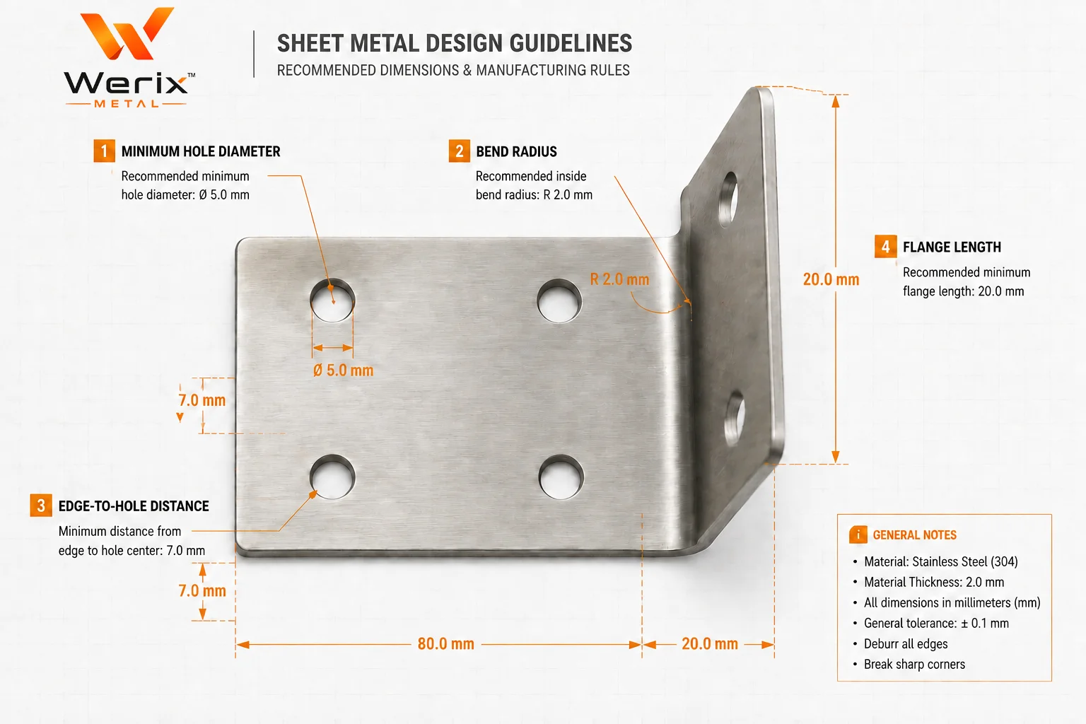
Hole diameter in sheet metal is constrained by the cutting process and the material thickness. For laser-cut holes, the practical minimum diameter is 1× the material thickness (1T) — below this, the hole quality degrades and the hole may not be round. For punched holes, the minimum punch diameter is typically 1T for mild steel and 1.5T for stainless steel and aluminum.
| Material | Laser Minimum | Punch Minimum | Recommended Minimum |
|---|---|---|---|
| CR Steel (0.5–3.0 mm) | 0.5 mm or 1T | 1T | 1T for structural |
| 304 Stainless (0.5–3.0 mm) | 0.5 mm or 1T | 1.5T | 1.5T — stainless work-hardens |
| AL 5052-H32 (0.5–3.0 mm) | 0.5 mm or 1T | 1.5T | 1.5T — aluminum tears if undersized |
| AL 6061-T6 (0.5–3.0 mm) | 0.5 mm or 1T | 2T | 2T — T6 temper is brittle at shear zone |
- Hole diameter should be at least 1× material thickness for laser cutting; 1–1.5× for punching
- For tapped holes, the pilot hole must leave enough material: M3 tap requires a 2.5 mm pilot in 1.5 mm+ material
- Hole-to-hole spacing: maintain at least 2T between adjacent holes to prevent distortion
- Countersunk holes require a minimum material thickness of 1.5× the countersink depth
- Oblong holes (slots): maintain a minimum width of 1T and corner radius of 0.5T
Bend Radius Rules
The inside bend radius is the single most important DFM parameter for formed sheet metal parts. Too tight a radius cracks the outer surface; too large a radius wastes space. The minimum bend radius depends on material type, temper, grain direction, and thickness. As a rule of thumb: the inside bend radius should be at least 1× material thickness (1T) for most materials in their standard temper.
| Material | Standard Temper Min Radius | Hard Temper Min Radius | Notes |
|---|---|---|---|
| CR Steel (SPCC) | 0.5T | 1T | Most forgiving material |
| 304 Stainless (annealed) | 0.5T | 1T–2T | Work-hardens rapidly |
| 316 Stainless (annealed) | 0.5T | 1T–2T | Slightly more ductile than 304 |
| AL 5052-H32 | 1T | 1.5T | Default aluminum for bent parts |
| AL 6061-T6 | 2T–4T | 4T+ | Very limited formability in T6 |
| Copper C110 | 0.5T | 1T | Highly ductile |
Grain Direction Matters
Sheet metal has a grain direction from the rolling mill. Bending perpendicular to the grain allows a tighter minimum radius — typically 0.5T versus 1T when bending parallel to the grain. Specify "grain direction: perpendicular to primary bends" on your drawing to avoid cracking.
Edge-to-Hole Distance Rules
Holes placed too close to a sheet edge distort during forming or become fragile in use. For laser-cut parts, the minimum is 1T or 0.5 mm, whichever is larger. For punched parts, the minimum is 1.5T. For holes near bends, the minimum distance from a hole edge to the bend line should be at least 3T + bend radius.
| Feature | Minimum Distance | Reason |
|---|---|---|
| Hole to sheet edge (laser) | 1T or 0.5 mm | Prevents edge warping from HAZ |
| Hole to sheet edge (punched) | 1.5T | Prevents punch breakout at edge |
| Hole to bend line | 3T + bend radius | Prevents hole ovaling during forming |
| Slot to bend line | 4T + bend radius | Slots distort more than round holes |
| Hole to hole (same plane) | 2T | Prevents web collapse between holes |
| Hole to corner (laser) | 1T or 0.5 mm | Prevents corner burn-through |
Tab and Slot Design Rules
Tab-and-slot joints are one of the most effective DFM techniques in sheet metal — they self-locate parts during assembly, eliminate jigs and fixtures, and can replace spot welds or fasteners for non-structural connections. The tab width should be at least 2× material thickness for adequate stiffness; the slot width should be tab width + 0.1 mm (laser) or + 0.2 mm (punch).
- Tab width: minimum 2T — thinner tabs bend during assembly and do not self-locate
- Slot width: tab width + 0.1 mm (laser) or + 0.2 mm (punch) — enough clearance for easy insertion
- Tab length: minimum 3T — shorter tabs do not provide adequate shear resistance
- Chamfer or radius on tab entry edge (0.5 mm) to guide insertion and prevent burr catching
- For load-bearing tab joints, use 3–4 tabs per joint to distribute shear load evenly
- Slot depth: minimum equal to tab length — shallower slots leave the tab proud of the surface
Uniform Bend Direction
In press brake bending, the part is positioned on a V-die and a punch presses the material into the V to create the bend. Each time the part is flipped to bend in the opposite direction, the operator must reposition and re-reference the part — adding 1–3 minutes per repositioning. Parts designed with all bends in the same direction can be formed in a single setup, reducing cycle time by 30–50%.
When opposite-direction bends are unavoidable, try to group them so that the part needs only one flip. For example, if a part has six bends — four up and two down — placing the two downward bends adjacent to each other allows a single flip between groups rather than alternating flips.
Practical Tip: Communicate Bend Sequence
If your drawing does not specify a bend sequence, the press brake operator will choose one — and it may not be the optimal one. Including a suggested bend sequence on your drawing reduces setup time and prevents dimensioning errors caused by cumulative tolerance stack-up.
When opposite-direction bends are unavoidable, try to group them so that the part needs only one flip. For example, if a part has six bends — four up and two down — placing the two downward bends adjacent to each other allows a single flip between the two groups rather than alternating flips after each bend.
Material Thickness Considerations
Material thickness cascades through every DFM parameter — minimum hole diameter, bend radius, flange length, and tab width are all expressed as multiples of thickness (T). Specifying a thicker gauge "for safety" increases cost on every dimension.
| Parameter | 0.8 mm Material | 1.5 mm Material | 3.0 mm Material |
|---|---|---|---|
| Min laser-cut hole | 0.8 mm | 1.5 mm | 3.0 mm |
| Min bend radius | 0.4–0.8 mm | 0.75–1.5 mm | 1.5–3.0 mm |
| Min flange length | 3.2 mm | 6.0 mm | 12.0 mm |
| Laser cutting speed (mild steel) | 25–30 m/min | 12–18 m/min | 4–8 m/min |
| Bend tonnage (per meter) | 15–25 tons | 35–50 tons | 80–120 tons |
Do Not Over-Specify Thickness
In our DFM reviews, we frequently encounter parts specified at 2.0 mm where 1.5 mm meets all structural requirements. A quick FEA check before finalizing gauge can save 15–25% on per-part cost.
Surface Finish Impact on Tolerances
Surface finishes add thickness to the part, which affects fit and tolerance. Powder coating adds 60–120 µm per surface; anodizing adds 5–25 µm (Type II) or 25–100 µm (hard anodize). These thicknesses affect hole diameters, slot widths, and tab/slot clearances.
| Finish | Thickness Added (per surface) | Tolerance Impact | DFM Consideration |
|---|---|---|---|
| Powder coating | 60–120 µm | Holes shrink by 0.12–0.24 mm | Oversize holes by 0.15–0.25 mm before coating |
| Anodizing (Type II) | 5–25 µm | Holes shrink by 0.01–0.05 mm | Account for build-up on close-tolerance fits |
| Hard anodize (Type III) | 25–100 µm | Holes shrink by 0.05–0.20 mm | Mask critical fits or machine after anodizing |
| Zinc plating | 5–15 µm | Holes shrink by 0.01–0.03 mm | Minimal impact — rarely needs compensation |
| Nickel plating | 5–25 µm | Holes shrink by 0.01–0.05 mm | Account for on press-fit holes |
Common DFM Mistakes and How to Fix Them
After reviewing thousands of customer designs, we see the same DFM mistakes recurring across industries. Below are the five most common issues, along with practical fixes.
- Mistake 1: Holes too close to bends (< 3T). Fix: move hole at least 3T + R from bend line, or add the hole after bending
- Mistake 2: Flanges shorter than 4T + R. Fix: increase flange length to at least 4T + bend radius
- Mistake 3: Tight tolerances on every dimension (±0.05 mm). Fix: relax general tolerances to ±0.2 mm; reserve tight tolerances for mating interfaces only
- Mistake 4: Inconsistent bend radii on the same part. Fix: standardize all bends to the same radius for a single die setup
- Mistake 5: No finish compensation on close-tolerance holes. Fix: oversize holes by 2× finish thickness before coating
DFM Review Is Free
At WERIX, DFM review is included with every quote — no charge, no obligation. Upload your STEP or DXF file and our engineering team will review the design for manufacturability and suggest cost-saving alternatives within 24 hours.
FAQ
Ditulis oleh
Tom
Senior Process Engineer
Insinyur manufaktur berpengalaman yang mengkhususkan diri dalam fabrikasi sheet metal, CNC machining, dan finishing permukaan. Menulis panduan praktis untuk membantu insinyur membuat keputusan pengadaan yang tepat.
Siap Memulai Proyek Anda?
Dapatkan umpan balik DFM dan penawaran harga dalam 24 jam. Tanpa jumlah pesanan minimum.